
This is my very first project when I was in college simply because it is simple and the parts are readily available. It can be easily built using breadboard or universal PCB because it only requires few components. It uses a very popular op-amp 741.
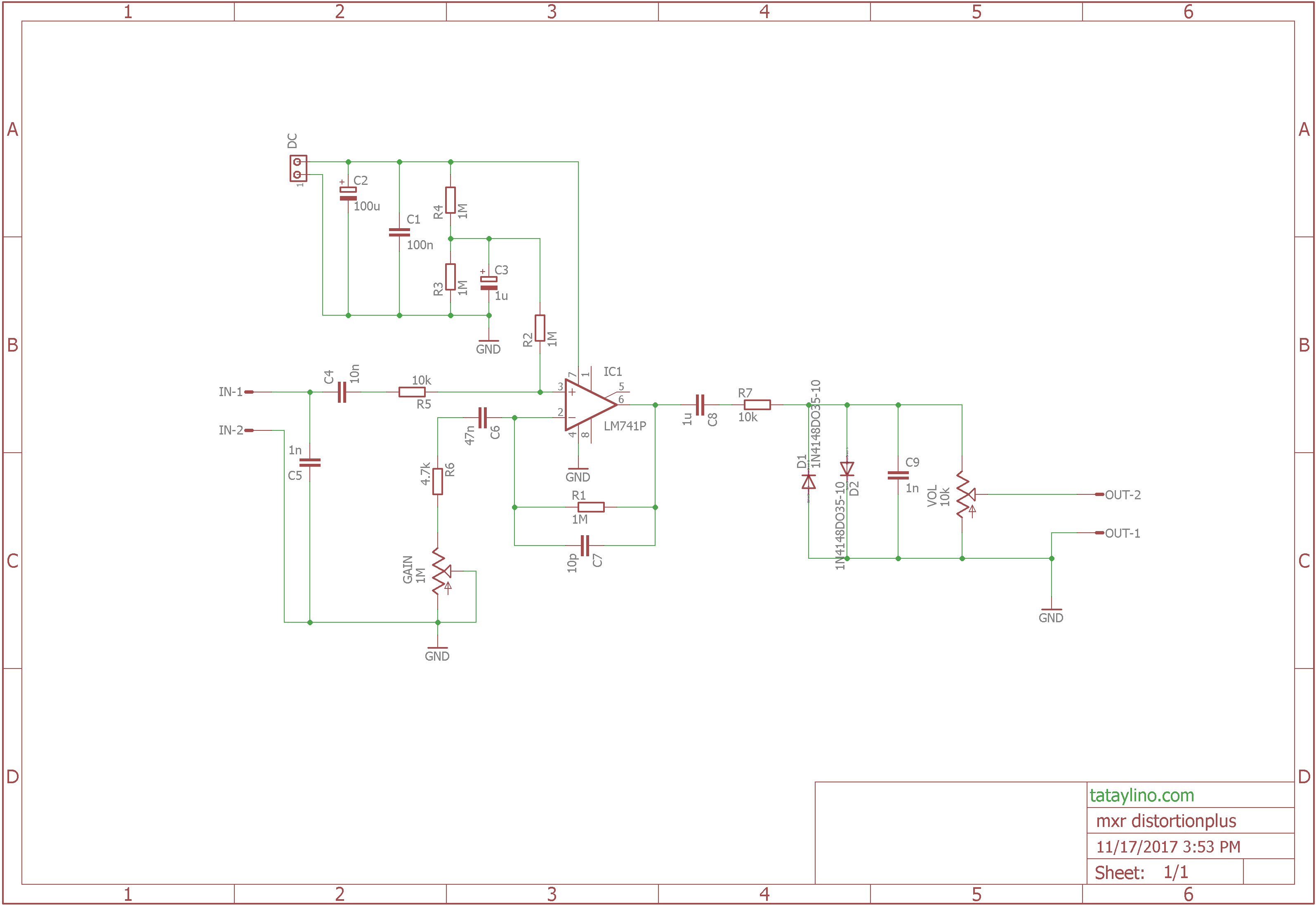
About the Circuit
The circuit only uses 1 op-amp and is powered by 9V battery. There are only 2 controls namely Gain and Volume.

Simulation Result

red – output
green – input
Input is set at 500mVpp at 500Hz, gain and volume set at 100%.
Frequency Response
The frequency response changes as you increase the gain. Treble becomes dominant on higher gain setting as you can see on the graph below.

blue – Gain = 0%
green – Gain = 50%
red – Gain = 100%
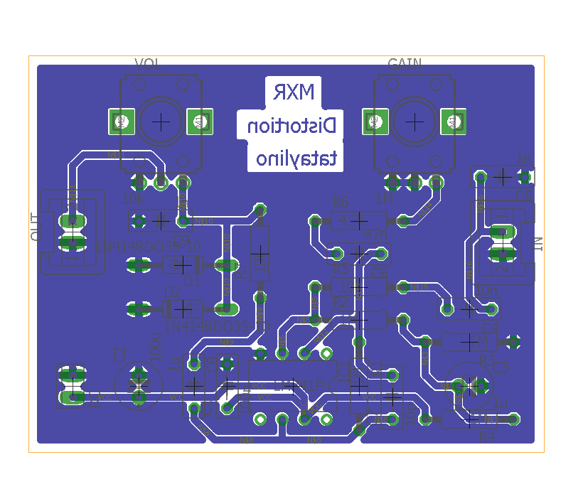
PCB Design
I have designed a simple PCB for those who want to build their own. As always I created it with eagle PCB. You can download this software for free as long as you won’t use it for commercial use. It also has a limitation on size.
DOWNLOADS:
Download page